Administrating P&ID – Plant Modeller integration
Integration between the Plant Modeller and P&ID applications requires the use of a Plant Modeller Service Instance.
Enable integration in project settings
Select the option Integration in use when creating the project or later in the Manage Project dialog, as described in Managing project settings.
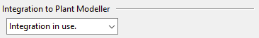
When this option is set, a Service Instance can be used to manage the integration data in the COS server.
Install a Plant Modeller Service Instance for integration
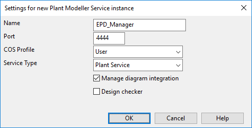
A Plant Modeller Service Instance is required for P&ID integration. When installing the Service Instance to a project, make sure you select the option Manage diagram integration. This setting specifies that the given Service Instance is responsible for managing the P&ID integration data in the project.
For general information about installing and configuring Plant Modeller Service Instances, see Plant Modeller services.
Configure attributes for integration
Define how attributes are used in integration.
Define integration attributes | Map database columns to integration attributes
Define integration attributes
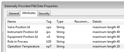
P&ID can publish to 3D the attributes that are assigned to the 'Externally Provided P&I Data' COS object type. In new projects, the attributes 'Valve Position Id', 'Instrument Position Id', and 'Equipment Position Id' are automatically included in integration, while in very old projects they might need to be configured manually.
Map database columns to integration attributes
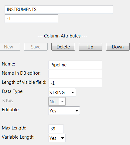
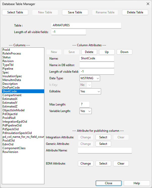
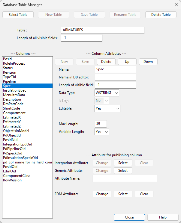
In the Integration Attribute setting of the Database Table Manager tool, map the selected database column to the integration attribute that should receive the column's value. The data type of the column must match the data type of the attribute.
-
In the Integration Attribute setting, click Select to create a new mapping or Change to modify the existing mapping.

The PosId column must always be mapped in the ARMATURES and EQUIPMENTS tables.
-
Map the PosId column of armatures to the 'Valve Position Id' (vpo) attribute.
-
Map the PosId column of equipment to the 'Equipment Position Id' (.n5) attribute.
The PosId column can also be mapped in the INSTRUMENTS table, if needed.
-
Map the PosId column of instruments to the 'Instrument Position Id' (ipo) attribute.
-
Make sure the Pipeline field is defined, or integration will not work.
Systems and pipelines are automatically included in integration, but additional attributes can be published for them by mapping database fields to attributes in the same way as for armatures, instruments, and equipment.
Configuring component model retrieval
P&ID can be configured to allow diagram designers to define which component model to use when a 3D designer inserts the object to the 3D model.
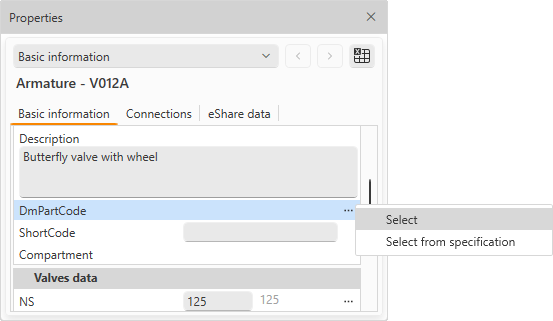
The COS object ID that specifies the component model for a 3D model object can be defined in the DmPartCode field of the integrated diagram object. There are three methods that diagram designers can use for this:
-
Select manually – In the DmPartCode field, the diagram designer uses the Select command to select a component model from the part library. This method may be used, for example, when piping specifications intentionally exclude valves and pipelines do not allow out-of-spec parts. Manual assignment gives the diagram designer the responsibility to select a suitable valve that meets the material requirements.
-
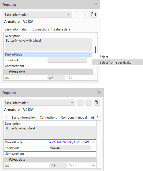
Select from specification – In the DmPartCode field, the diagram designer uses the Select from specification command to select a component model from the specification; this action automatically populates the ShortCode field. This method may be used when the piping specification includes the exact valve to use.
-
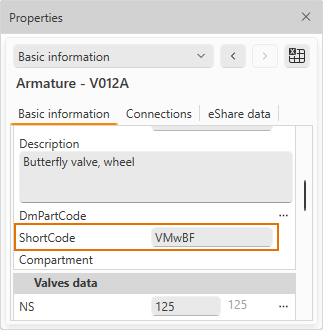
Pre-fill short code – In the ShortCode field, the diagram designer can directly type the short code to use. This method may be used when piping specifications do include valves but the given component model is not available yet, or its actual provider has not been decided by the time the diagram design must be done. This method allows the diagram designer to specify the functional design for a valve whose exact model will be confirmed later and which will be added to the specification once the material choices have been done.
Using the methods above requires the following configuration:
-
The ShortCode and Spec columns are present in the ARMATURES and INSTRUMENTS tables.
-
Functional codes include the ShortCode to use.
-
Object templates include one or more diagram object templates with a Menu Item Data definition that matches a LookupKey in the component lookup table.
-
Component lookup table includes an entry that specifies the ShortCode or CModel (component model) to use. Either field can be utilized.
-
Specifications include the required part sizes of the specified component model.
As a result:
-
Inserting a new diagram object retrieves the component model's COS object ID.
-
Updating integration data from P&ID to 3D creates an integration object (EPD) that includes the ShortCode as hard-coded data.
-
In Plant Modeller, inserting the integration object to the 3D model selects the correct component model from the library.
-
In external integration using the Web API, the ShortCode can be utilized with the combination of defined specification for an EPD with valve position ID and pipeline.
Publish location and compartments from P&ID to Plant Modeller
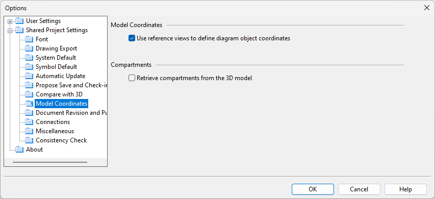
In File > Settings > Shared Project Settings > Model Coordinates, you can control the automatic calculation of model coordinates and compartments for diagram objects.
-
If Use reference views to define diagram object coordinates is selected and P&ID includes a reference view, inserting a new diagram object inside the reference view calculates its location in the 3D model in reference coordinates and stores it in the EstimatedX, EstimatedY and EstimatedZ database fields, if present in the ARMATURES, EQUIPMENTS, and INSTRUMENTS tables. Also the estimated length of pipe runs is calculated and stored in the EstimatedLength database field, if present in the PIPES table.
- If also Retrieve compartments from the 3D model is selected, the associated compartment's name is assigned to the diagram object and stored in the Compartment database field name database field.
Using the integration data in Plant Modeller
No additional configuration is required in Plant Modeller to use the integration data published by P&ID.
The tools used to insert standard components and equipment automatically detect integration objects in COS and display them to the user.
The attribute data published by P&ID to integration objects is automatically inherited by the linked model objects.